10 Pin Out Address
This topic goes over how 8086 creates addresses and how data transfers occurs
Intro
8086 can be divided mainly into
- Bus Interface Unit
- Execution Unit
Externals
ROM - Read-Only Memory
contains the BIOS (Basic Input/Output System)
RAM - Random Access Memory is faster and hence, applications get loaded here during runtime
Permanent Memory is non-volatile
IO- Input/Output Devices
Buses
| Address | Data | Control | |
|---|---|---|---|
| Direction | 1 | 2 | 1 |
All signals depend on the clock. So faster the frequency of the clock, faster the operations.
Address Buses
They are multiplexed with data lines and with selection lines. To reduce area required.
Multiplexing happens with inputs that won’t be used simultaneously.
Pin Diagram
40 pins
Dual Inline Package IC
VCC
\(5v \pm 10 \%\)
GND
2 grounds
Clk
One cycle of this clock is called as T state.
The time between 2 rising/falling edges is called as a time period.
Reset
Used to initialize the processor. The processor will repeat all given instructions. Any data inside registers will be lost, and flags will be reset.
CS FFFFh
IP 0000h
This signal has to high for atleast 4 clk signals.
\(MN/ \overline{MX}\)
Minimum/Maximum
These 2 are different modes of operations.
ALE
Address Latch Enable
Whenever there is address, this is set as high. Else, it is data.
This is sent to Gate signal.
\(\overline{BHE}/S7\)
Bus High Enable
Enables the most significant data lines (D8 - D15), only when required
S7 is always high
Modes
| Minimum | Maximum | |
|---|---|---|
| Logic | 1 | 0 |
| No of processors | 1 Only 8086 or 8088 | Multiple requires 8087 as its co processor for floating point operation |
| Size | Smaller | Larger |
| Cost | Cheaper | Costlier |
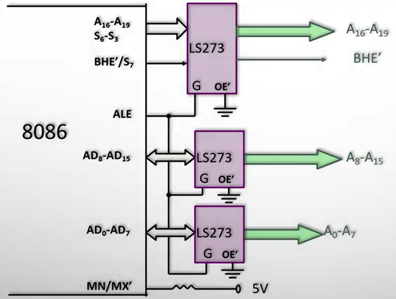
Octal Latch
8 bit latch
used for de -multiplexing address and data
it is used to ensure that address does not get affected, while operations don’t get affected.
we are using LS273
G
Gate Signal controls whether or not input to the latch get reflected to the output.
As soon as the address gets passed through, the signal is turned low.
get its value from the ALE
When \(G\) is high, address is sent out. Else, data is sent out.
\(\overline{OE}\)
Output Enabled Active Low
Grounded by default
Don’t know
| Signal | Address Signal | Status Signal |
|---|---|---|
| \(A_{16}/S_3\) | \(A_{16}\) | Segment Address |
| \(A_{17}/S_4\) | \(A_{17}\) | Segment Address |
| \(A_{18}/S_5\) | \(A_{18}\) | Int Flag Status |
| \(A_{19}/S_6\) | \(A_{19}\) | 0 |
| \(\overline{BHE}/S_7\) | \(\overline{BHE}\) | 1 |
| S4 | S3 | Function |
|---|---|---|
| 0 | 0 | Extra Segment |
| 0 | 1 | Stack Segment |
| 1 | 0 | Code or no Segment |
| 1 | 1 | Data Segment |