11 Pin Out Control Data
Data Bus
Pins
\(M/\overline{IO}\)
Differentiate between memory and IO access.
When high, memory reference instructions.
When low, IO instructions.
\(\overline{RD}\)
When it is low, read operation takes place.
It is an ouput signal.
\(\overline{WR}\)
When it is low, write operation takes place.
It is an ouput signal.
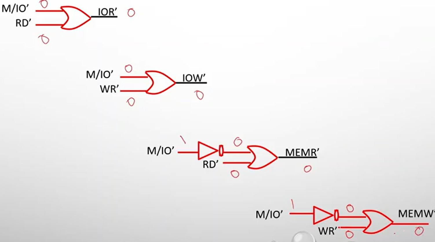
| \(M/\overline{IO}\) | \(\overline{RD}\) | \(\overline{WR}\) | Bus Cycle |
|---|---|---|---|
| 1 | 0 | 1; | Memory Read |
| 1 | 1 | 0 | Memory Write |
| 0 | 0 | 1 | Input/Output Read |
| 0 | 1 | 0 | Input/Output Write |
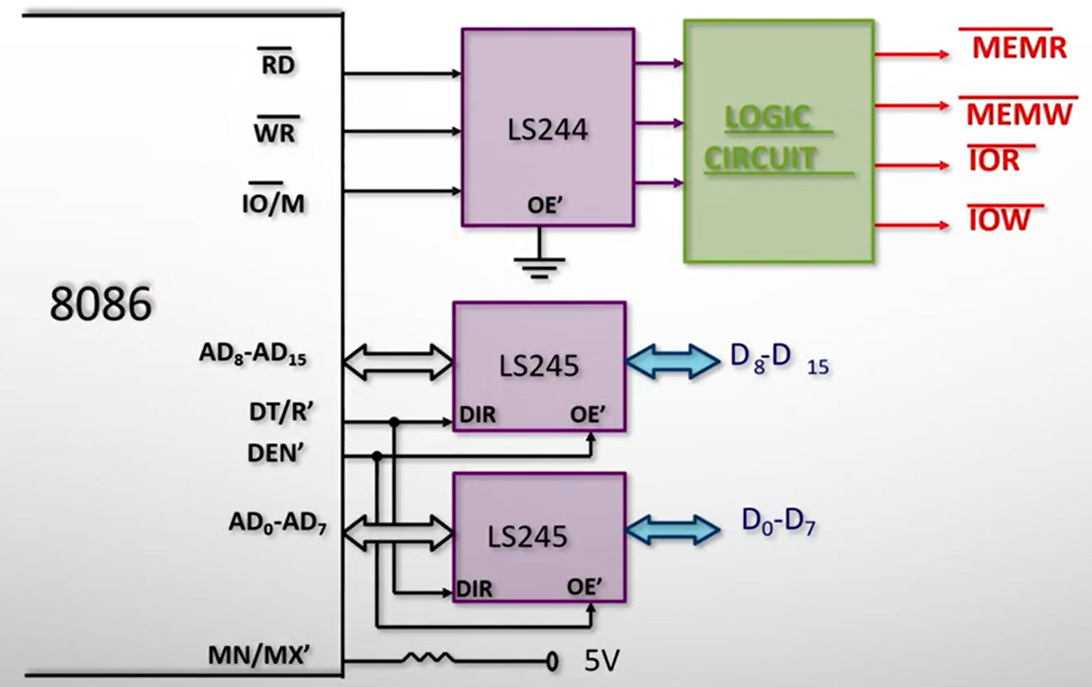
\(\overline{DEN}\)
Data Enable
Whenever data is available on \(AD0- AD15\), this signal becomes low, to signal that data is coming.
Connected to \(\bar E\)
\(DT/\overline{R}\)
Data Transmit/Receive
Controls the direction of data transfer from/to data transceivers, such as Bi-Directional Buffer.
When high, data transmitted by processor
When low, data received by processor
Connected to DIR
Bi-Directional Buffer
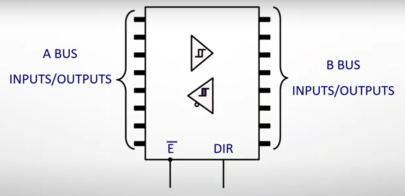
We are using LS245 as the octal buffer.
Bus A = MP, Bus B = Data Bus
Data can move from Bus A \(\to\) B, or vice-versa.
\(\bar E\)
Connected to \(\overline{DEN}\)
DIR
Connected to \(DT/\overline{R}\)