13 Machine Cycles
Cycles
Instuction cycle is the time taken by the processor to execute one instruction.
As 8086 is a CISC processor, each instruction cycle consists of multiple machine cycles.
Each machine cycle consists of T states.
All operations occur sequentially, controlled by the clock signal.
Machine Cycles
flowchart LR
1[Instruction Fetch] --> 2[Instruction Decode] --> 3[Operand Fetch] --> 4[Instruction Execution] --> 5[Store] --> 1
T State
Time Period = \(\frac{1}{\nu}\)
Getting from/to Register does not require anything
Timing Diagram
Tutorial
Machine Cycles
Getting from/to Register does not require anything The number of bits readable in 1 cycle = 16bits 1. opcode - 16bits requires 2 - 1. Reading from memory = 1 1. Writing to memory = 1
Time
Total Time = No of T States \(\times\) Duration of each T state = No of cycles \(\times\) No of T States in each cycle \(\times\) Duration of each T state
No of T states in each cycle = 4 Duration of each T state = 1 Time Period = \(\frac{1}{\nu}\)
2 memory operations
- Read (Data/Instruction)
- Write (Data)
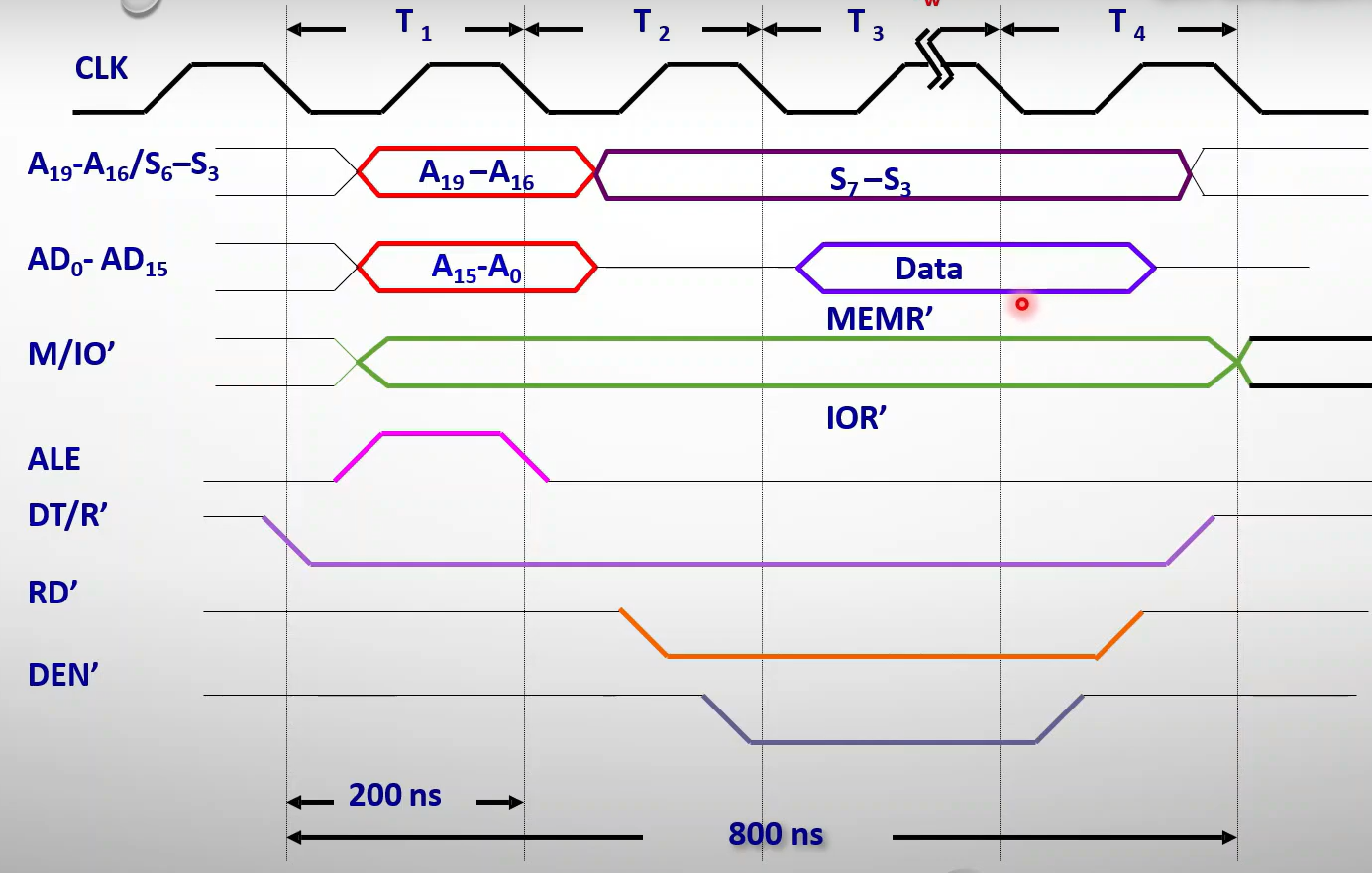
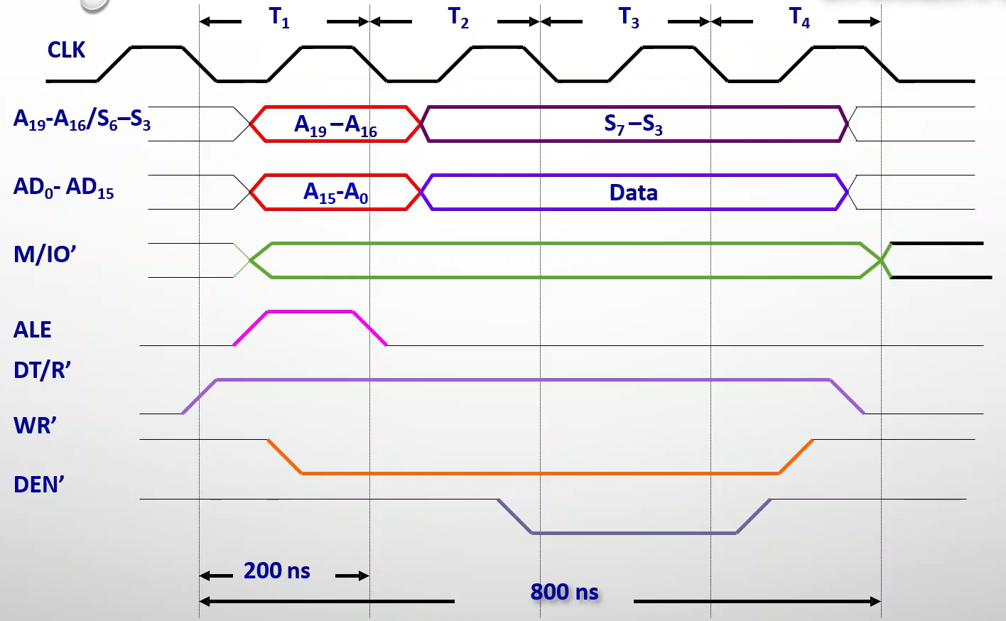
Timing Diagram
In write operation, the data is available in the 2nd state itself, as there will not be any delay.
In read operation, it is available in the 3rd state.
Slow Device
Active High signal from slow device/memory, acknowledging that it is ready for data transfer.
Else, the processor inserts a wait state, before \(T_3\) state.
Number of wait states depends on the difference in the speed between the microprocessor and the slow device.
Read/Write
Write
Read