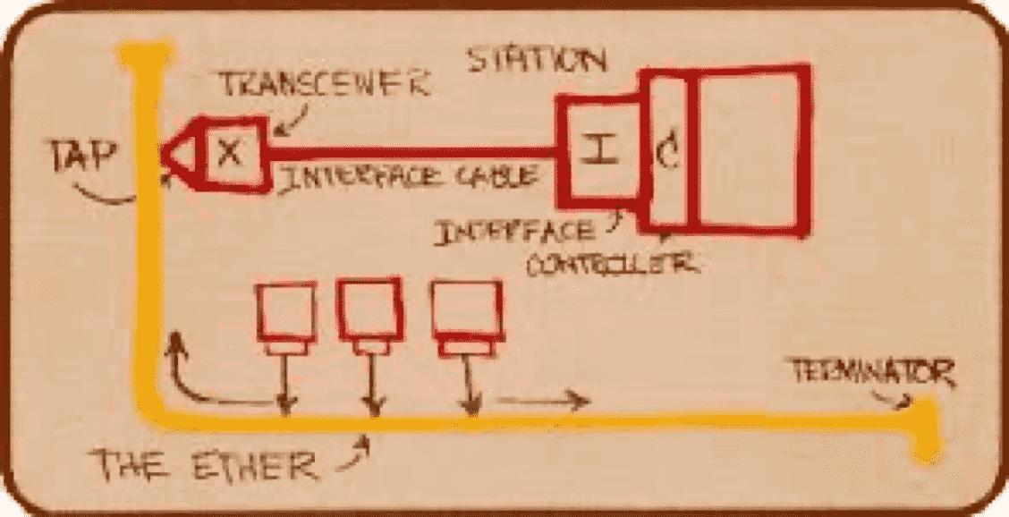
08 Ethernet
Protocol for connecting multiple computer systems to form a LAN, with protocols to
- control passing of information
- avoid simultaneous transmission by multiple systems
IEEE 802.3 Data Link Layer Sublayers
| Datalink Sublayer | Tasks | Name of frame | Implementation | Protocol |
|---|---|---|---|---|
| LLC (Logical Link Control) | Error Control Flow Control Interconnectivity b/w data link layer of different LANs Multiplex multiple network layer protocols in frame | IEEE 802.3 | Software | CRC (error-correction) ARQ |
| MAC (Medium Access Control) | Framing MAC Addressing Medium Access Control | IEEE 802.2 | Hardware | Token-Passing (Wired Token Ring) CSMA/CD (Wired other) CSMA/CA with NAV (Wireless) |
Diagram
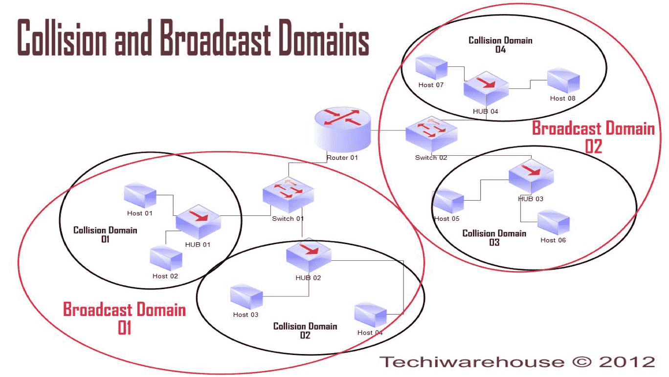
Domains
| Domain | Associated with | Number | |
|---|---|---|---|
| Broadcast | Router Connection | No of switches connected to router | |
| Collision | Switch Connection | No of half-duplex links connected to switch | Collision occurs as switches are not as intelligent as routers |
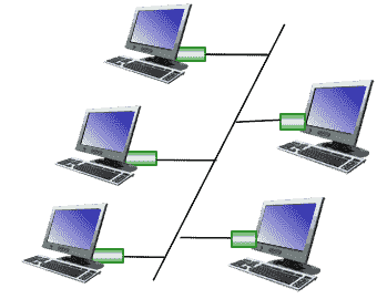
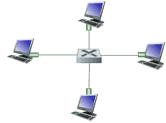
Topology
| Bus | Star | |
|---|---|---|
| Active switch in center | ||
| Collision domain | All nodes in same collision domain | Each spoke runs separate Ethernet protocol |
| Collisions Prevented? | ❌ | ✅ |
 |  |
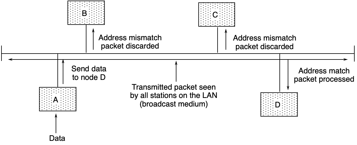
Normal Ethernet Operation
| Receiver receives frame with | |
|---|---|
| Matching destination address | Data sent to network layer |
| Broadcast address (e.g. ARP packet) | Data sent to network layer |
| Neither of the above | Discard frame |
Types
| Type | Speed | Connection | Reliable? | Chance of dropping frames | Access Protocol |
|---|---|---|---|---|---|
| Standard | 10 Mbps | Connectionless | ❌ | High | CSMA/CD |
| Fast | 100 Mbps | ||||
| Gigabit | 1 Gbps | ||||
| Ten-Gigabit | 10 Gbps |
Standard Ethernet Implementations
| Implementation | Topology | Transmission Medium |
|---|---|---|
| 10Base5 | Bus | Thick coaxial |
| 10Base2 | Bus | Thin coaxial |
| 10Base-T | Star | UTP (Unshielded-Twisted-Pair) |
| 10Base-F | Star | Fiber |
Steps of Routing to another LAN
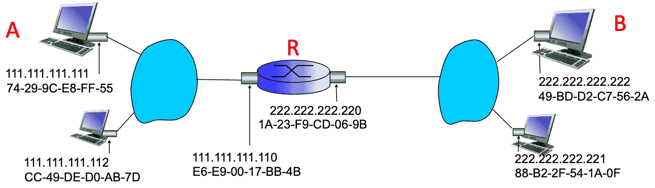
Assuming A has all the required addresses already, and wants to send a message to B via R.
- Create packet in Network Layer with
- Source address = A’s IP address
- Destination address = B’s IP address
- Create frame in Datalink Layer with
- Source address = A’s MAC address
- Destination address = R’s receiving terminal MAC address
- A sends message to R
- R receives message
- R processes and removes frame in Datalink Layer
- R processes packet in Network Layer
- R forwards packet with the same source and destination as before in the Network layer
- R creates frame in the Network layer with
- Source address = R’s sending terminal MAC address
- Destination address = B’s MAC address
Ethernet Switch
- Examines incoming frame’s MAC address
- Selectively forwards frame to one/more outgoing links when frame is to be forwarded on segment
- Uses CSMA/CD to access segment
- Buffers packets
Every host has dedicated & direction connection to switch
Each link connected to switch is its own collision domain; hosts transmitting simultaneously does not affect other transmissions if they are on different link.
Characteristics
- Transparent: Hosts are unaware of presence of switches
- Plug-and-Play device: No configuration required by network admin
- Self-Learning mechanism
Types
| Cut-through | Store-and-forward switch | |
|---|---|---|
| Begins forwarding data after examining | only first part of header | entire data |
| Retransmission Time | \(< T_t\) | \(= T_t\) |
Switch Table
Helps switch data from source to destination
| Host MAC Address | Interface to reach host | TTL |
|---|---|---|
Self-Learning
-
Check if receiver exists in switch table
-
If yes, go to step 5
-
‘Flood’ (broadcast) message to all stations
-
Update switch table with receiver’s entry
- Send to receiver
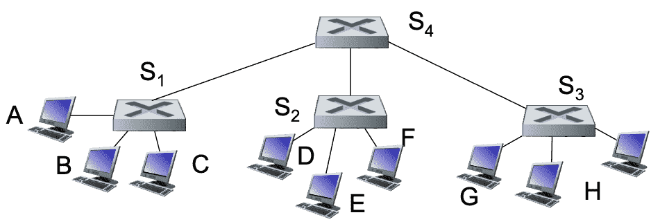
Interconnected Switches
Works using the same self-learning process
Switches vs Router
| Switch | Router | |
|---|---|---|
| Store & Forward? | ✅ | ✅ |
| Layer | Data Link | Network |
| Examine | Data link layer headers | Network layer headers |
| Understand addresses | MAC | IP |
| Forwarding Table? | ✅ | ✅ |
| Learning Method | Flooding learning | Routing algorithms |
VLAN
Virtual Local Area Network
Allows us to divide a LAN without any additional switches
VLAN can be defined using one of the following techniques
- Switch port
- MAC addresses of endpoints
Advantages
VLAN helps overcome the following
- Improve traffic isolation: frames by default can only travel within their own VLAN
- Dynamic membership: ports can be dynamically assigned among VLANs
- Efficient use of switches
- Management of users
- Forwarding between VLANS
- Address Security, privacy and efficiency issues. Data link layer broadcast traffic (ARP, DHCP, unknown location of destination MAC address) need not cross entire LAN.
Port-Based VLAN
| Details | Trunk Port connected to router Traffic isolation something else |
| No of usable ports | \(n-1\) (Trunk port unusable) |
| Actual connections | 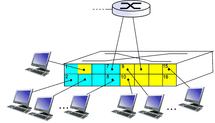 |
| Behaves as | 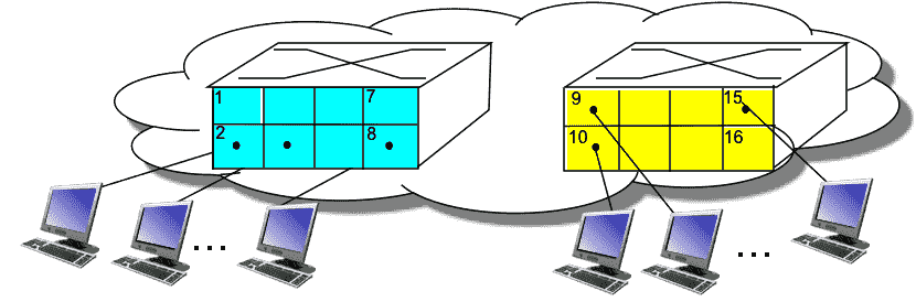 |
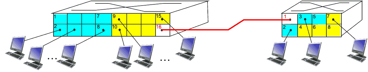
Trunk Port
Carries frames between VLANS defined over multiple physical switches. Frames forwarded over multiple switches must carry VLAN ID info as well, and hence uses IEEE 802.1Q Frame.
Ethernet/IEEE 802.1 Frame
All sizes shown in Bytes
| Size | |
|---|---|
| Minimum | 64 Bytes |
| Maximum | 1518 Bytes |
| Preamble | SFD (Start Frame Delimiter) | Dest MAC Address | Source MAC Address | Type | Payload (Data & Padding) | CRC |
|---|---|---|---|---|---|---|
| 7 Bytes | 1 byte | 6 Bytes | 6 Bytes | 2 Bytes | \([46, 1500]\) Bytes | 4 Bytes |
| Alternating 1/0 1010…1010 | 10101010**11** | Type of Data | Cyclic Redundancy Check | |||
| Part of physical layer header (Processed at physical layer) | Part of physical layer header (Processed at physical layer) | 0800 –> IPv4 0806 –> ARP Frame 8100 –> IEEE 802.1Q Frame 86DD –> IPv6 | Error -> Frame dropped | |||
| Synchronizes sender & receiver clock rates | Signals the beginning of frame |
Example of multiple frames

Receiver Address Type
| Type | Receiver Address Value |
|---|---|
| Unicast | LSB of first byte = 0 |
| Multicast | LSB of first byte = 1 |
| Broadcast | All bits are 1 |
LSB = Least Significant Bit
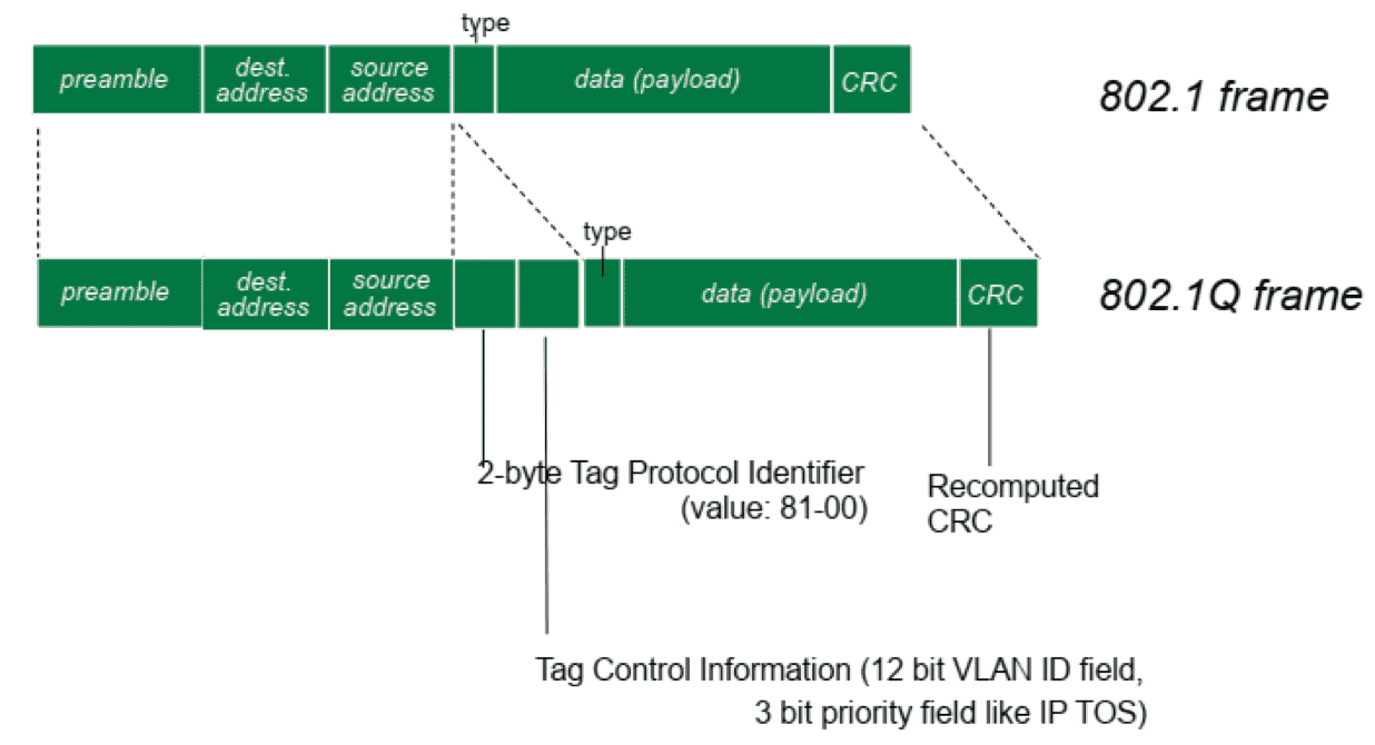
IEEE 802.1Q Frame
Adds/removes additional header fields for frames forwarded between trunk ports
(Empty cells of the following table means that they are the same as regular Ethernet frame)
| Preamble | SFD (Start Frame Delimiter) | Dest Address | Source Add | Tag Protocol Identifier | Tag Control Info | Type | Data & Padding | CRC |
|---|---|---|---|---|---|---|---|---|
| 2B | 12bits VLAN ID field 3bits field like IP TOS | Recomputed CRC | ||||||
| 81-100 |
VLAN Frame
| Preamble | SFD (Start Frame Delimiter) | Dest MAC Address | Source MAC Address | Tag | Type | Payload (Data & Padding) | CRC |
|---|---|---|---|---|---|---|---|
Tag is